
16.8 MW Data Center — Southeastern US
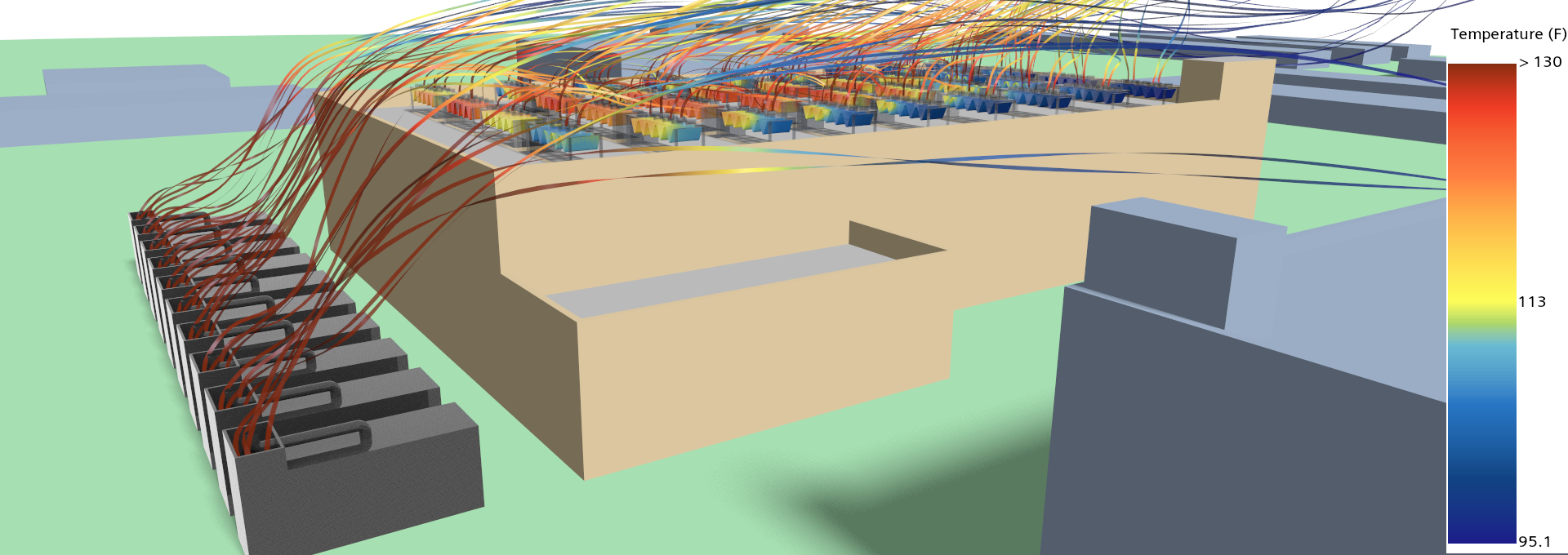
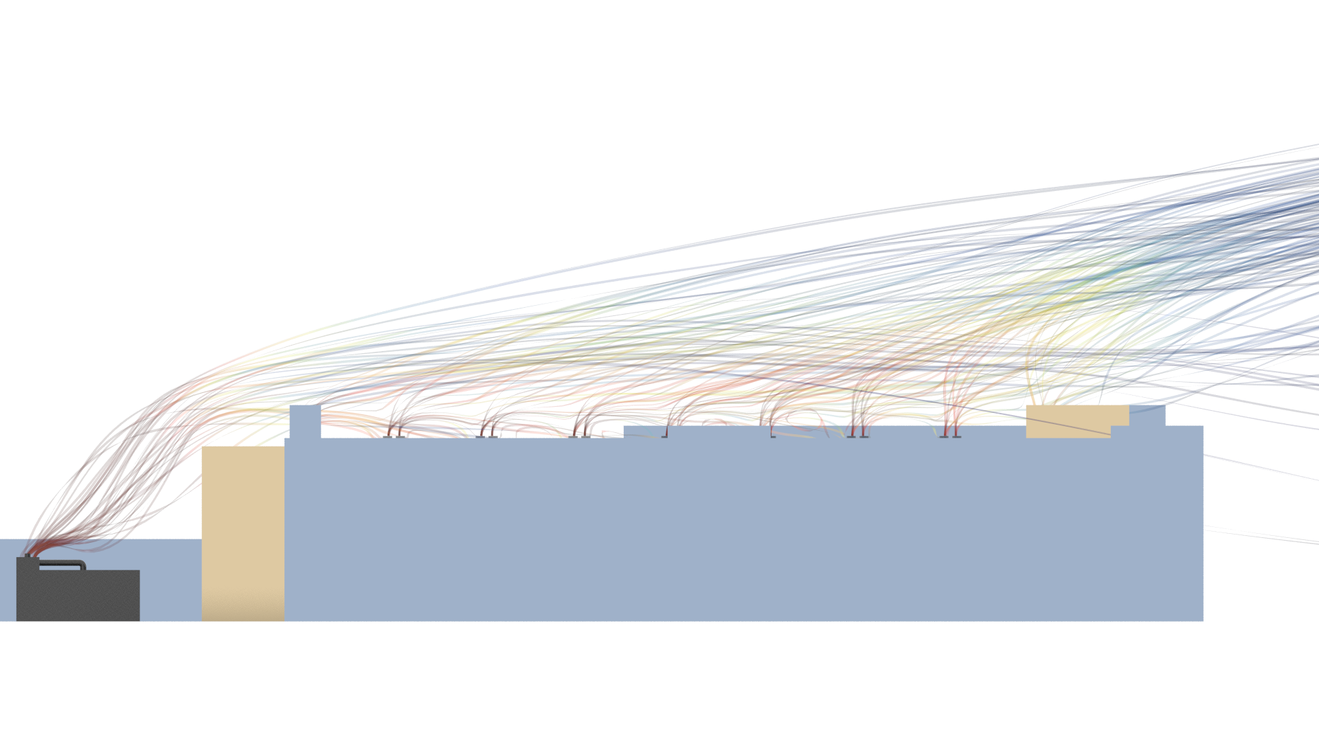
Generators beneath the chillers: a ground-level generator row sits directly under the west rooftop chiller array, and under a westerly wind the exhaust follows a short, direct path into the intakes above. Public-source inputs. Screening-level.
What this page covers
This page presents a screening-level exterior CFD analysis of a 16.8 MW data center in the Southeastern United States, developed by a major colocation operator and engineered by a national firm with a dedicated mission-critical practice. Heat rejection is a large rooftop air-cooled chiller array; the standby generators sit at grade in a row along the west side — directly beneath the west end of that array.
The result is a short, direct recirculation geometry. Under a westerly wind, the generator exhaust has very little distance to travel before it reaches the chiller intakes above it — and in a hot, humid summer climate, that re-ingested air erodes the capacity of an air-cooled plant.
Facility context
The facts below are derived entirely from cited public sources: published facility and provider materials, aerial and street-level imagery, and public terrain data. No proprietary drawings, specifications, or operational data are used. Identifying details are withheld; the facility is described by type and configuration only.
- Region.
- Southeastern United States (hot, humid design climate).
- Owner-operator.
- A major colocation operator. Not identified here.
- Engineer of record.
- A national engineering firm with a dedicated mission-critical practice. Not identified here.
- Critical IT capacity.
- 16.8 MW critical (22 MW electrical service), N+1 redundancy.
- Cooling.
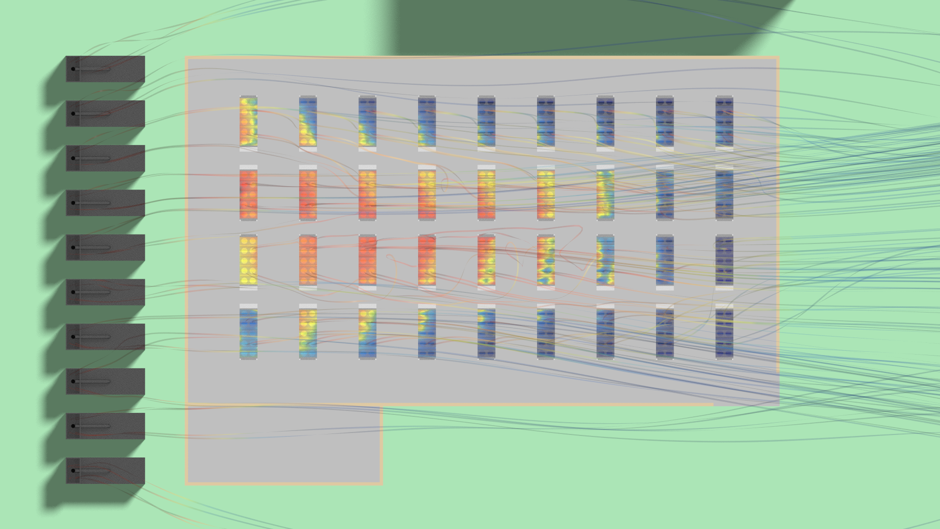
- 36 rooftop air-cooled chillers in four rows of nine, vertical discharge.
- Backup power.
- 10 diesel standby generators in a ground-level row along the west side, directly beneath the west chiller array.
Scenario presented
- Wind and ambient.
- Operating scenario.
Wind from the west at 10 mph, 92°F ambient — near the regional summer design condition. This vector carries the west-side generator exhaust up into the chiller array directly above it.
All generators and all chillers running at full load — the on-generator condition that maximizes both the exhaust source and the heat-rejection demand together.
This case was isolated by a directional sweep across the full compass — not the standard four-point (N/S/E/W) check. As with any generators-beneath-chillers layout, the governing variable is the vertical adjacency more than the wind: the exhaust source sits under the intakes.
What the model shows
The observations below are qualitative readings of the presented scenario. Quantitative outputs — per-unit intake temperatures, recirculation magnitudes — are shared with the owner's team on request.
- A short, direct recirculation path. With the generator row directly beneath the west chiller array, exhaust is drawn straight up into the chillers above rather than dispersing — the shortest exhaust-to-intake path a layout can produce.
- West-side intakes run markedly hotter. The west-side chiller intakes see local temperatures well above the downwind units, concentrated where the array sits over the generator enclosures.
- Intake dry-bulb governs capacity. Air-cooled chiller performance tracks intake dry-bulb directly, so the recirculation translates immediately into lost heat-rejection headroom — a first-order effect, not a rounding error.
- Best caught while layout choices are still open. This is the kind of exposure that is inexpensive to resolve on the drawing — a placement or orientation change — and expensive to remedy once built. The question worth putting to the engineering team: was the generators-beneath-chillers relationship modeled at the design ambient, or assumed adequate?
Methodology
The methodology applied here is the same standardized exterior CFD approach applied to every facility in the cohort — cylindrical far-field domain, logarithmic atmospheric boundary layer inlet, polyhedral mesh in Siemens STAR-CCM+, realizable k-ε RANS baseline. The presented case uses a 92°F ambient. Full domain setup, boundary conditions, solver choices, and stated limitations are documented at the Methodology page. Key terms are defined at the Key Terms and FAQ page.
Disclosure. This is independent research conducted by Resolved Analytics. All inputs are derived from cited public sources; no proprietary drawings, specifications, or operational data are used. The facility is described by type and configuration only and is not identified. Results represent idealized exterior conditions and do not represent the actual as-built performance of any facility. No claims are made regarding life-safety, code compliance, or operational performance. This material is not engineering services rendered to any party.