Rooftop Chiller CFD Modeling:
Simulation Guide for HVAC Cooling Systems
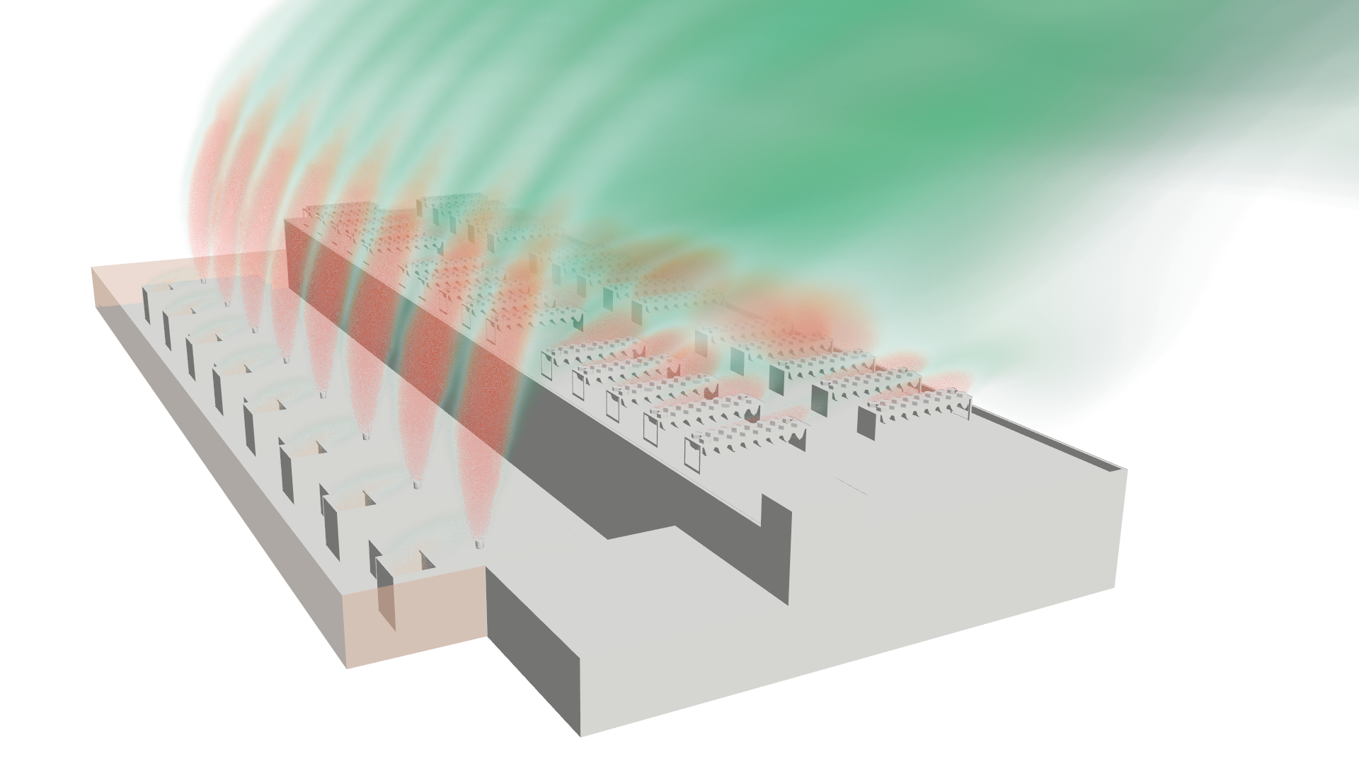
CFD modeling of rooftop chiller systems uses computational fluid dynamics to predict airflow patterns, heat rejection performance, and thermal interactions between chiller units, building exhaust, and ambient wind conditions. These simulations help mechanical engineers and facility designers optimize chiller placement, evaluate recirculation risk, and verify that cooling plant performance meets design specifications under realistic operating conditions — before equipment is installed or relocated.
What Is Rooftop Chiller CFD and When Is It Needed?
Rooftop chiller systems reject heat to the outdoor environment through air-cooled condensers or cooling towers. Their performance depends heavily on the local airflow environment — which is affected by building geometry, adjacent equipment, wind direction, and the thermal plumes from neighboring units.
CFD modeling becomes necessary when:
Chiller recirculation is suspected or observed. Hot exhaust air from one chiller unit is drawn back into the condenser intake of the same unit or an adjacent unit, reducing cooling capacity and increasing energy consumption.
New equipment placement is being planned. The physical spacing, orientation, and grouping of rooftop chillers significantly affects performance — CFD predicts whether a proposed layout will cause recirculation or wind-induced performance degradation before installation.
Building geometry creates complex wind patterns. Tall parapets, penthouse structures, adjacent buildings, or rooftop obstructions can redirect airflow in ways that trap hot exhaust plumes near condenser intakes.
Performance does not match design specifications. When installed chillers underperform on hot days or under specific wind conditions, CFD identifies whether the root cause is recirculation, insufficient clearance, or wind-induced intake starvation.
Energy optimization is a priority. Quantifying the energy penalty from recirculation allows facility managers to evaluate targeted interventions (baffles, screens, unit relocation) against their cost.
What Data Do You Need for a Rooftop Chiller CFD Model?
Equipment Data:
Chiller make, model, and rated capacity
Condenser fan airflow rate and discharge velocity
Condenser coil face area and inlet locations
Exhaust discharge direction (vertical, horizontal, or angled)
Number of units and their grouping/spacing
Site Geometry:
Building roof dimensions and height
Parapet wall heights
Penthouse, stairwell, and mechanical room locations
Adjacent building heights and distances
Rooftop obstructions (satellite dishes, solar panels, ductwork)
Operating Conditions:
Design day ambient temperature
Prevailing wind speed and direction (local meteorological data)
Seasonal wind variation if year-round performance matters
Part-load operating scenarios (how many units run simultaneously under typical vs. peak conditions)
Performance Targets:
Maximum allowable condenser inlet temperature rise above ambient
Minimum required cooling capacity under design conditions
Energy efficiency targets (kW/ton or COP)
How Is a Rooftop Chiller CFD Model Set Up?
The simulation workflow for rooftop chiller applications differs from enclosed environments like data centers:
Domain Definition
The computational domain must extend well beyond the building footprint to correctly capture wind approach profiles and allow exhaust plumes to develop naturally. A domain extending 5-10 building heights in each direction is typical. Adjacent buildings that may influence rooftop wind patterns must be included.
Wind Modeling
Inlet boundary conditions apply an atmospheric boundary layer velocity profile — wind speed varies with height according to terrain roughness. Multiple wind directions are typically simulated (at minimum: prevailing, worst-case, and calm conditions) since chiller recirculation severity is strongly wind-dependent.
Heat Source Representation
Each chiller condenser is modeled as a volumetric heat source with specified airflow rate. The exhaust plume buoyancy (hot air rising) must be captured, requiring temperature-dependent density treatment in the solver.
Turbulence and Buoyancy
Standard RANS turbulence models (realizable k-epsilon or SST k-omega) are appropriate for most rooftop applications. Buoyancy effects are critical — without proper buoyancy modeling, the simulation will not correctly predict whether hot exhaust rises and dissipates or recirculates back to condenser intakes.
Multi-Scenario Analysis
Unlike a single-condition data center model, rooftop chiller studies typically require simulating 4-8 wind scenarios (varying direction and speed) plus a calm-wind worst case. The calm condition is often the most critical for recirculation.
Common Mistakes in Rooftop Chiller CFD
Domain too small
If the computational domain does not extend far enough from the building, wind patterns and plume behavior are artificially constrained, producing misleading results.
Ignoring buoyancy
Hot exhaust plumes rise due to buoyancy. A simulation that treats air as constant-density will incorrectly predict plume behavior and overestimate recirculation.
Single wind direction only
Recirculation severity varies dramatically with wind direction. A model that only tests the prevailing wind may miss the worst-case scenario.
No calm-wind case
On still days, buoyant plumes rise vertically and may be drawn down into adjacent units by condenser fan suction. This is often the worst recirculation condition and must be simulated separately.
Nameplate airflow instead of measured
Condenser fan performance degrades with filter loading, altitude, and age. Using nameplate airflow rates overstates exhaust velocity and underestimates recirculation risk.
Omitting adjacent structures
Nearby buildings, cooling towers, or rooftop structures create wake zones that trap hot air. The model must include these to be realistic.
When to Hire a Consultant vs. Model In-House
Hire a consultant when:
The project involves complex building geometry with multiple rooftop obstructions or adjacent structures
Wind-dependent performance analysis requires multi-scenario CFD runs with atmospheric boundary layer modeling
The cooling plant investment exceeds $500,000 and the cost of a design error (equipment relocation, capacity shortfall) justifies independent expert analysis
You need results suitable for design review documentation or commissioning verification
Build in-house when:
Your organization manages a portfolio of buildings with recurring chiller placement decisions
The rooftop configurations are relatively simple (open roof, adequate clearances, no complex wind interactions)
An engineer with CFD experience is available and can dedicate time to this analysis alongside other simulation work
The cost consideration:
A rooftop chiller CFD study typically costs $10,000-$20,000 for a single building with 4-8 wind scenarios. Compared to the cost of relocating chillers that suffer from recirculation ($50,000-$200,000+ including crane, rigging, piping modifications, and downtime), the simulation investment is modest.