
24 MW Data Center — Midwestern US
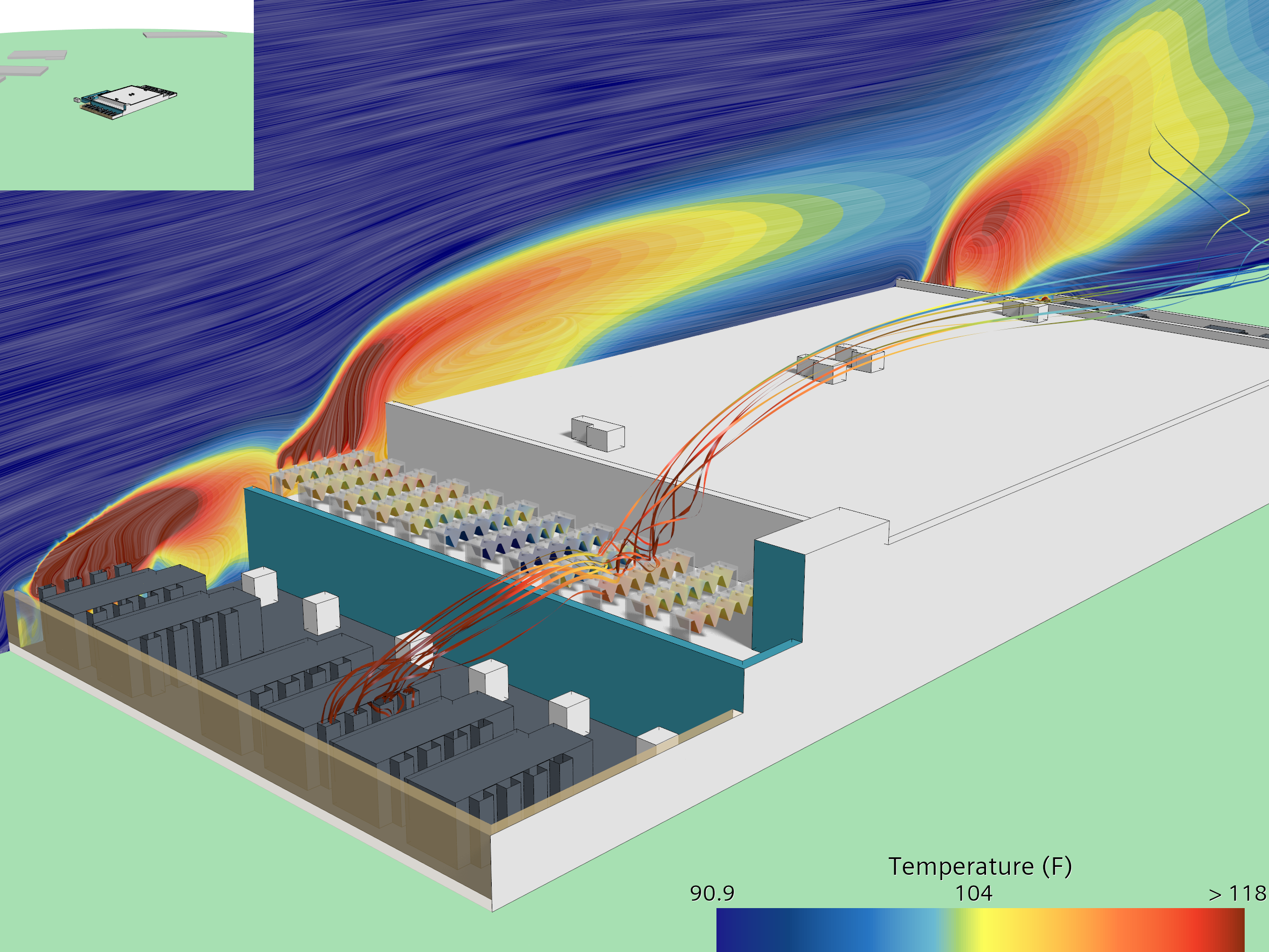
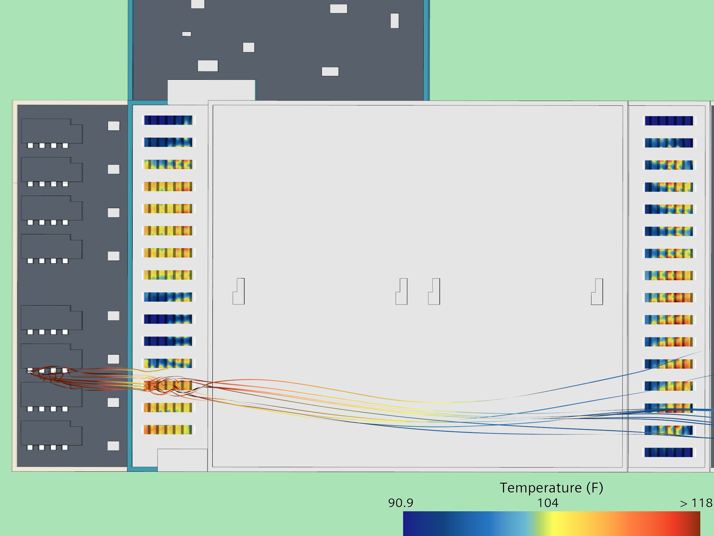
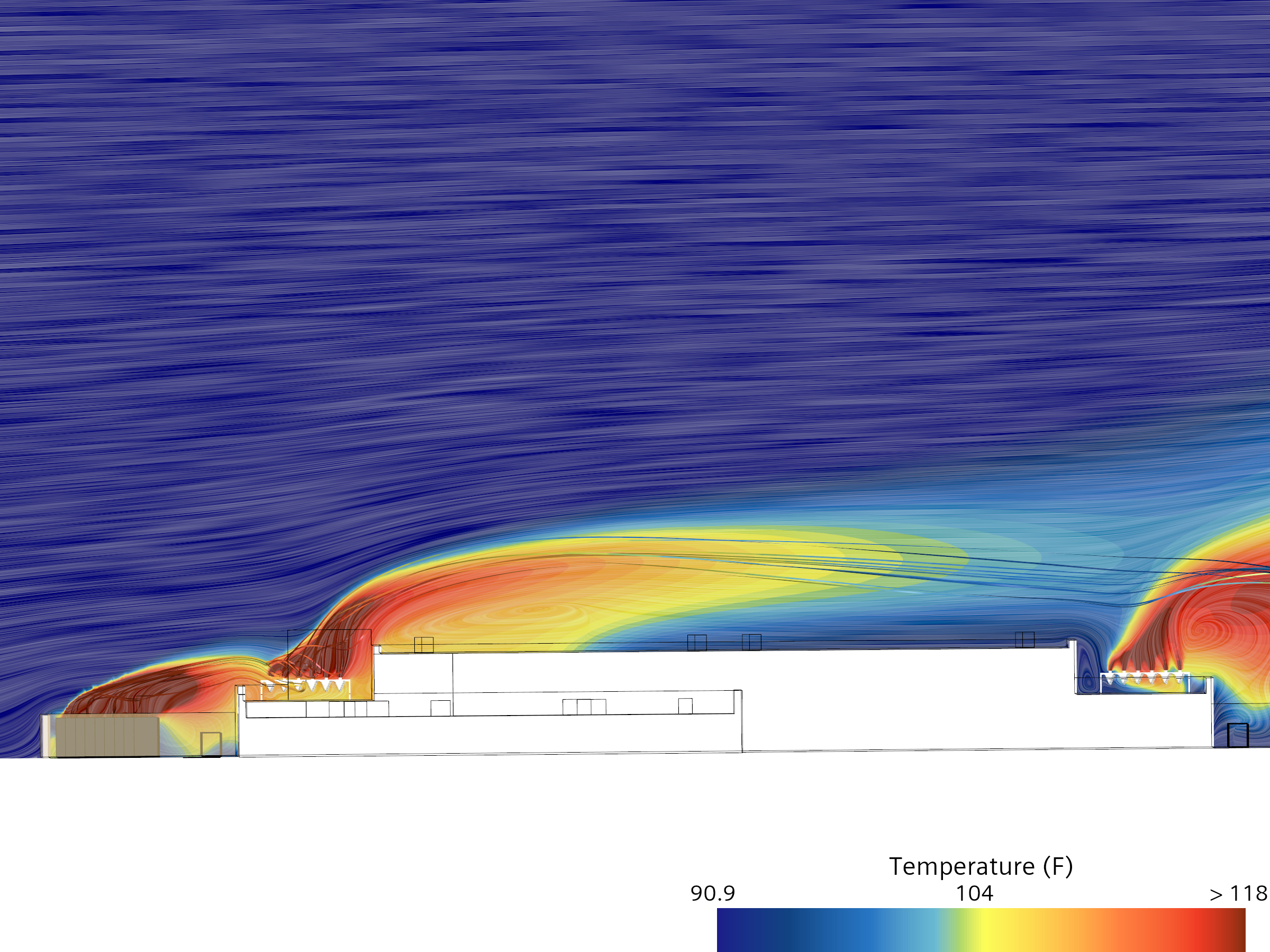
Waterless dry-cooler recirculation: under a northeasterly wind, ground-level generator exhaust reaches the rooftop dry-cooler intakes — and the site's symmetry means the opposite wind drives a mirror-image exposure. Public-source inputs. Screening-level.
What this page covers
This page presents a screening-level exterior CFD analysis of a 24 MW data center in the Midwestern United States, developed by a major colocation operator and engineered by a national firm with a dedicated mission-critical practice. It is a waterless campus: heat rejection is handled by closed-loop, air-cooled rooftop dry coolers — no cooling towers, no water consumed — and the standby generators sit at grade, in a layout symmetric about the building's long axis.
The result is a recirculation question with a twist: because the site is symmetric, the exposure comes in matched pairs. Under a northeasterly wind, exhaust from the upwind generator group reaches the dry coolers — and a southwesterly wind produces the mirror image.
Facility context
The facts below are derived entirely from cited public sources: published facility and provider materials, aerial and street-level imagery, and public terrain data. No proprietary drawings, specifications, or operational data are used. Identifying details are withheld; the facility is described by type and configuration only.
- Region.
- Midwestern United States.
- Owner-operator.
- A major colocation operator. Not identified here.
- Engineer of record.
- A national engineering firm with a dedicated mission-critical practice. Not identified here.
- Critical IT capacity.
- 24 MW, N+1 redundancy.
- Building.
- Two-story, purpose-built campus.
- Cooling.
- Waterless: rooftop dry coolers (closed-loop glycol, air-cooled) in two arrays, northeast and southwest; side-draw intakes through V-coil faces, vertical discharge. No cooling towers; no water consumed.
- Backup power.
- Ground-level generator enclosures on concrete pads, split into northeast and southwest groups with stack exhaust. Site layout is symmetric about the building's long axis.
- Electrical service.
- 138 kV transmission to 34.5 kV building distribution.
Scenario presented
- Wind and ambient.
- Operating scenario.
Wind from the northeast (45°) at 10 mph, 98°F ambient — a high-end regional summer condition that carries the northeast generator group's exhaust toward the dry-cooler array.
All generators and all rooftop dry coolers running at full load — the on-generator condition that maximizes both the exhaust source and the heat-rejection demand together.
This case was isolated by a directional sweep across the full compass — not the standard four-point (N/S/E/W) check. The site's symmetry is the point: whatever the northeasterly wind does to one array, a southwesterly wind does to the other.
What the model shows
The observations below are qualitative readings of the presented scenario. Quantitative outputs — per-unit intake temperatures, recirculation magnitudes — are shared with the owner's team on request.
- Generator exhaust impinges on the rooftop dry coolers. Under the northeasterly wind, the plume from the upwind ground-level generator group rises and reaches the rooftop dry-cooler intakes rather than dispersing clear of the roof.
- The risk is symmetric. Because the generator groups and dry-cooler arrays mirror each other about the building's long axis, a southwesterly wind drives an equivalent exposure on the opposite array — two adverse vectors, not one.
- Waterless cooling raises the stakes on intake air. With no evaporative process to fall back on, dry-cooler capacity tracks intake dry-bulb directly, so warmed intake air translates straight into lost heat-rejection headroom — making intake air quality a first-order design concern here.
- Building geometry governs whether exhaust reaches the roofline. Whether the ground-level plume clears the roof edge or washes onto the arrays is set by massing and spacing — a question an exterior model resolves and an interior one takes as fixed.
Methodology
The methodology applied here is the same standardized exterior CFD approach applied to every facility in the cohort — cylindrical far-field domain, logarithmic atmospheric boundary layer inlet, polyhedral mesh in Siemens STAR-CCM+, realizable k-ε RANS baseline. The presented case uses a 98°F ambient. Full domain setup, boundary conditions, solver choices, and stated limitations are documented at the Methodology page. Key terms are defined at the Key Terms and FAQ page.
Disclosure. This is independent research conducted by Resolved Analytics. All inputs are derived from cited public sources; no proprietary drawings, specifications, or operational data are used. The facility is described by type and configuration only and is not identified. Results represent idealized exterior conditions and do not represent the actual as-built performance of any facility. No claims are made regarding life-safety, code compliance, or operational performance. This material is not engineering services rendered to any party.