
16 MW Data Center — Mid-Atlantic US
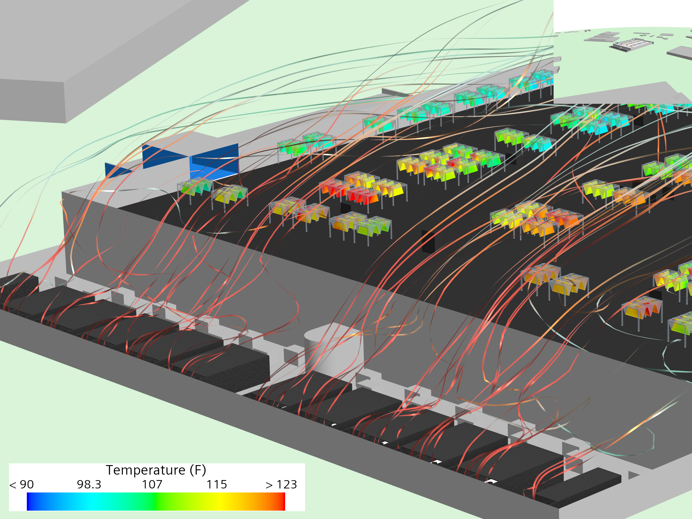
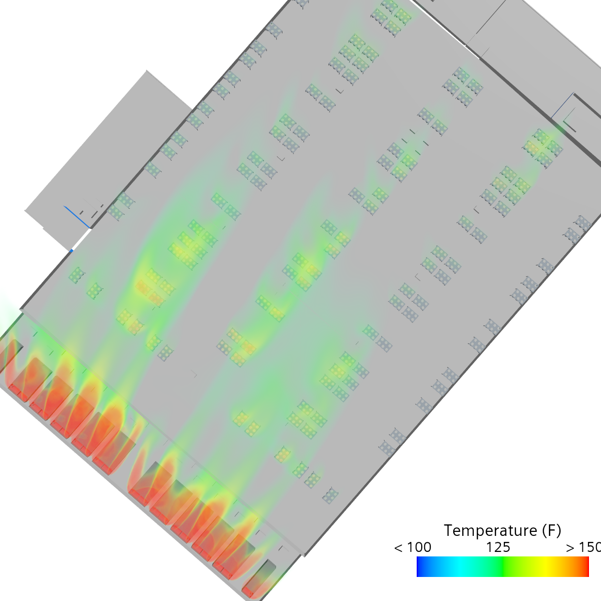
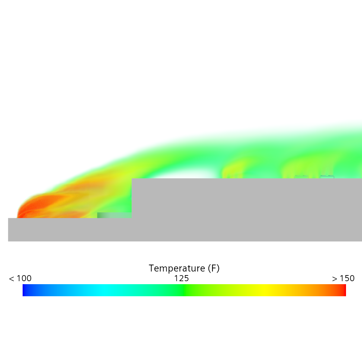
Generator exhaust impingement under a southwesterly wind: ground-level generator exhaust lofts onto the rooftop heat-rejection array, driving the central units toward their shutdown threshold. Public-source inputs. Screening-level.
What this page covers
This page presents a screening-level exterior CFD analysis of a 16 MW data center in the Mid-Atlantic United States, developed by a major colocation operator and engineered by a national A+E firm with a dedicated mission-critical practice. The facility uses waterless, pumped-refrigerant heat rejection on the roof — no cooling towers and no chilled-water loop — with the standby generators in a ground-level yard along the south building face.
The result is a ground-to-roof impingement question. Under a southwesterly wind, exhaust from the ground-level generator yard rises and reaches the rooftop heat-rejection array — the kind of exterior interaction a standard four-point wind check can miss and an interior thermal model never sees.
Facility context
The facts below are derived entirely from cited public sources: published facility and provider materials, aerial and street-level imagery, and public terrain data. No proprietary drawings, specifications, or operational data are used. Identifying details are withheld; the facility is described by type and configuration only.
- Region.
- Mid-Atlantic United States.
- Owner-operator.
- A major colocation operator. Not identified here.
- Engineer of record.
- A national A+E firm with a dedicated mission-critical practice. Not identified here.
- Critical IT capacity.
- 16 MW across six data vaults.
- Building.
- Two-story, purpose-built; approximately 112,000 SF of data floor.
- Cooling.
- Waterless, pumped-refrigerant rooftop heat rejection, N+2 redundancy. No cooling towers, no chilled-water loop. Treated in a chiller-style abstraction for intake-temperature analysis.
- Backup power.
- 22 diesel generators in two pods of eleven ("eleven to make ten"), in a ground-level yard along the south building face.
- Electrical service.
- 34.5 kV distribution, two redundant utility feeds.
Scenario presented
- Wind and ambient.
- Operating scenario.
Wind from the southwest (215°) at 10 mph, 105°F ambient — a high-end summer design condition. Of the directions screened, this is the one that lofts the ground-level generator exhaust onto the rooftop array.
N+R: all generators and all heat-rejection units running concurrently at full plant load — the on-generator condition that maximizes both the exhaust source and the heat-rejection demand together.
This case was isolated by a directional sweep across the full compass — not the standard four-point (N/S/E/W) check — which is the only way a specific vector like this one surfaces at all. The full wind-case matrix is available to the owner's team on request.
What the model shows
The observations below are qualitative readings of the presented scenario. Quantitative outputs — per-unit intake temperatures, recirculation magnitudes — are shared with the owner's team on request.
- Ground-level exhaust reaches the rooftop array. Under the southwesterly wind, the plume from the ground-level generator yard on the south face rises along the building and impinges on the rooftop heat-rejection units rather than dispersing clear of the roof.
- Central-array intakes approach shutdown thresholds. Across the central portion of the rooftop array, local intake temperatures approach ~125°F — the regime where shutdown setpoints engage on standard air-cooled platforms — from the re-ingested exhaust.
- Ground-to-roof plume geometry drives the exposure. With generators at grade and heat rejection on the roof, the governing question is whether the exhaust column lofts high enough, under the wrong wind, to reach the array — a massing-and-adjacency problem an exterior model resolves and an interior one takes as fixed.
- A question for the design team. An independent exterior model surfaces the one direction and location worth watching before it is built in, and frames the question worth putting to the engineering team on every project: were the adverse, non-standard wind vectors modeled explicitly, or only the standard design-day condition?
Methodology
The methodology applied here is the same standardized exterior CFD approach applied to every facility in the cohort — cylindrical far-field domain, logarithmic atmospheric boundary layer inlet, polyhedral mesh in Siemens STAR-CCM+, realizable k-ε RANS baseline. The presented case uses a 105°F ambient. Full domain setup, boundary conditions, solver choices, and stated limitations are documented at the Methodology page. Key terms are defined at the Key Terms and FAQ page.
Disclosure. This is independent research conducted by Resolved Analytics. All inputs are derived from cited public sources; no proprietary drawings, specifications, or operational data are used. The facility is described by type and configuration only and is not identified. Results represent idealized exterior conditions and do not represent the actual as-built performance of any facility. No claims are made regarding life-safety, code compliance, or operational performance. This material is not engineering services rendered to any party.