
18 MW Data Center — South Central US
A robust exterior layout: a ground-level heat-rejection plant that keeps generator exhaust clear of the chiller intakes across a range of wind directions — with one localized item to watch. Public-source inputs. Screening-level.
What this page covers
This page presents a screening-level exterior CFD analysis of an 18 MW data center in the South Central United States, developed by a major operator and engineered by a national firm with a dedicated mission-critical practice. Unlike most facilities in the cohort, it keeps its heat-rejection plant at grade — a ground-level arrangement of air-cooled chillers, cooling towers, and packaged units, with the rooftop carrying only exhaust fans. Backup generators sit in a fenced perimeter yard on the west side.
The headline is a favorable one. The exterior layout holds up well across a range of wind conditions, keeping chiller intakes within range in most cases. This page presents the one direction that produced a localized exception — and documents the robustness alongside it.
Facility context
The facts below are derived entirely from cited public sources: published facility and provider materials, aerial and street-level imagery, and public terrain data. No proprietary drawings, specifications, or operational data are used. Identifying details are withheld; the facility is described by type and configuration only.
- Region.
- South Central United States.
- Owner-operator.
- A major data-center operator. Not identified here.
- Engineer of record.
- A national engineering firm with a dedicated mission-critical practice. Not identified here.
- Critical IT capacity.
- 18 MW critical UPS load; approximately 1,500 W/SF density; ~1.3 PUE.
- Building.
- ~261,000 SF, single-story, purpose-built, 24-ft ceilings, pressurized raised floor.
- Cooling.
- Ground-level plant: air-cooled chillers, cooling towers, and packaged units on a closed-loop condenser-water system with free-cooling. Rooftop carries exhaust fans only.
- Backup power.
- 9 diesel generators in a fenced perimeter yard on the west side, in a northwest and a southwest group, with stack and radiator discharge.
Scenario presented
- Wind and ambient.
- Operating scenario.
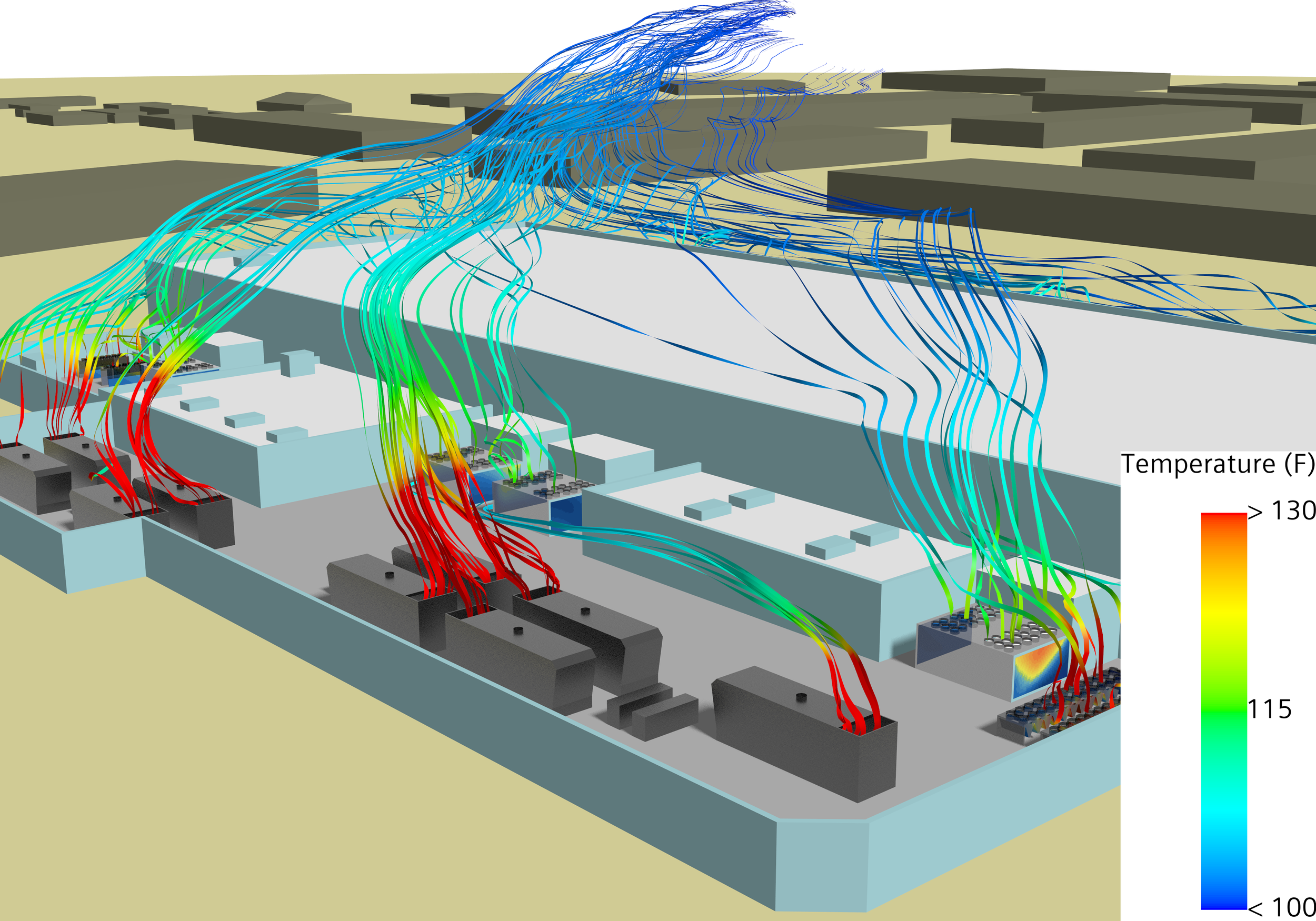
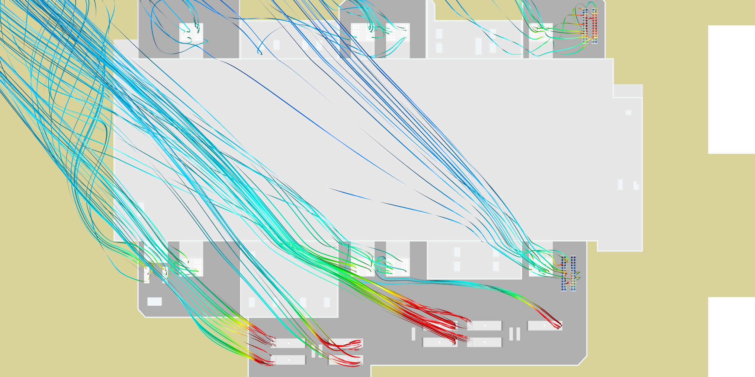
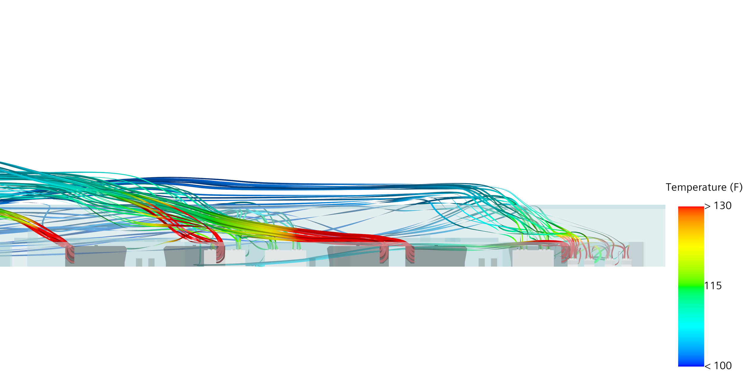
Wind from the southeast (135°) at 20 mph, 92°F ambient. Of the directions screened, this is the one that produced a localized exception at the eastern chiller bank.
All generators and all chillers running at full load — the on-generator condition that maximizes both the exhaust source and the heat-rejection demand together.
This case was isolated by a directional sweep across the full compass — not the standard four-point (N/S/E/W) check — which is the only way a narrow, specific vector like this one surfaces at all. The layout held up across the other directions screened; the full matrix is available to the owner's team on request.
What the model shows
The observations below are qualitative readings of the presented scenario. Quantitative outputs — per-unit intake temperatures, recirculation magnitudes — are shared with the owner's team on request.
- The exterior layout is robust. Across the wind directions screened, the site keeps generator exhaust largely clear of the chiller intakes. The at-grade separation between the west-side generator yard and the cooling plant, combined with the building massing, disperses exhaust before it reaches most of the heat-rejection equipment. This is a favorable result, and worth documenting as such.
- One localized exception, under a southeasterly wind. With wind from the southeast, a single area on the eastern chiller bank sees elevated local intake temperature. The effect is localized and modest — a small item rather than a systemic one — but it is the kind of edge case a directional screening exists to surface.
- Ground-level heat rejection changes the exposure. With chillers at grade rather than on the roof, the recirculation question is grade-to-grade: whether the generator yard's exhaust reaches the cooling plant across the site, rather than lofting onto a roof. This layout handles that well in most directions, which is itself a useful design data point.
- A documented baseline — and a question for the next build. For a facility that performs well, an independent exterior model is on-the-record confirmation of thermal robustness — and it pinpoints the one direction and location worth watching should the design or load ever change. It also frames the question worth putting to the engineering team on every future project: were the adverse, non-standard wind vectors modeled explicitly, or only the standard design-day condition?
Methodology
The methodology applied here is the same standardized exterior CFD approach applied to every facility in the cohort — cylindrical far-field domain, logarithmic atmospheric boundary layer inlet, polyhedral mesh in Siemens STAR-CCM+, realizable k-ε RANS baseline. The presented case uses a 92°F ambient. Full domain setup, boundary conditions, solver choices, and stated limitations are documented at the Methodology page. Key terms are defined at the Key Terms and FAQ page.
Disclosure. This is independent research conducted by Resolved Analytics. All inputs are derived from cited public sources; no proprietary drawings, specifications, or operational data are used. The facility is described by type and configuration only and is not identified. Results represent idealized exterior conditions and do not represent the actual as-built performance of any facility. No claims are made regarding life-safety, code compliance, or operational performance. This material is not engineering services rendered to any party.